Joint Space Definition
In WOS, the definition of a robotic arm's joint space adheres to the manufacturer’s original settings, including parameters such as the minimum and maximum values for each joint, directionality, and the maximum and minimum speeds. We have opted to use Radians as the unit of measure in WOS, so all angle-related interactions within the user interface are denoted in Radians.
WOS currently supports two types of robotic arms: those with 6 degrees of freedom (6DOF) and those with 7 degrees of freedom (7DOF). In the joint space, these two configurations are fundamentally similar; one simply operates with an array of six values, while the other works with seven.
Joint Direction and Measurement
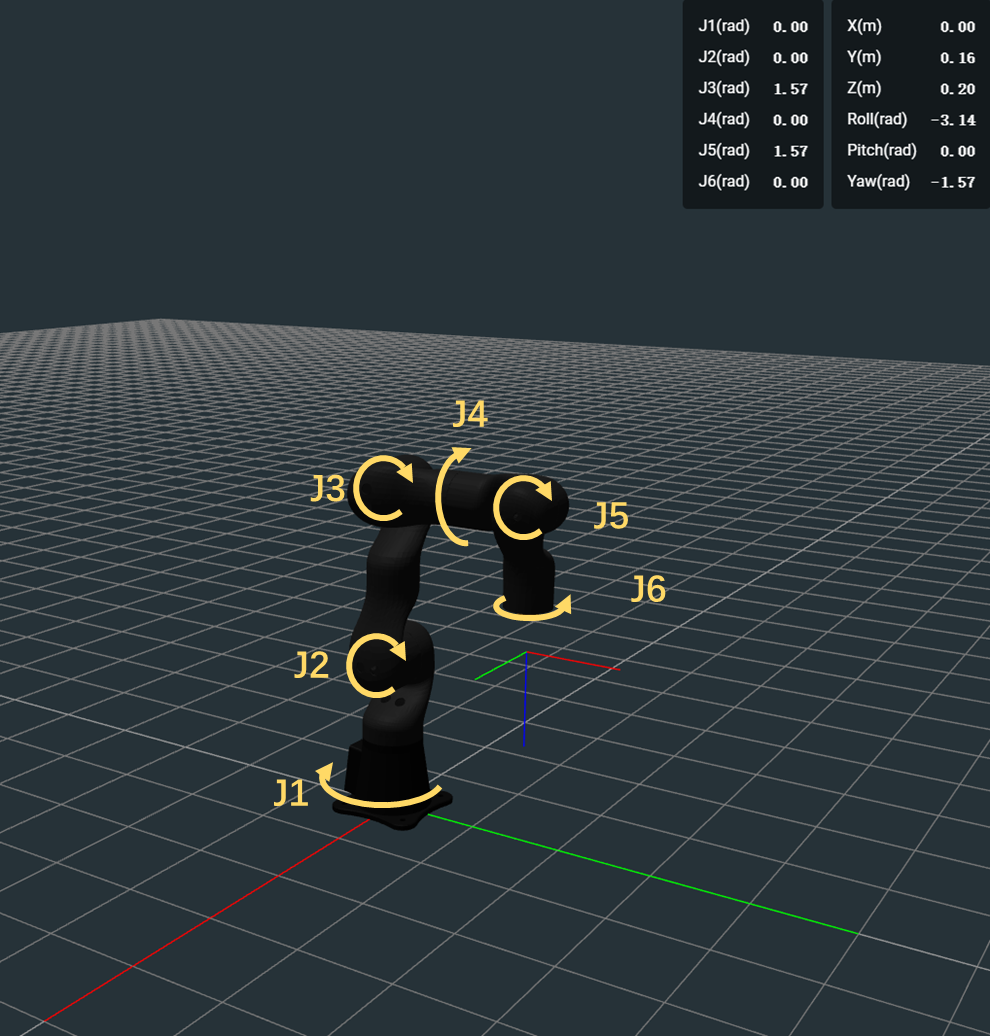
Taking the STR400 as an example, the direction of joint angles aligns with the official manual from Jacode Robotics. Consider the illustration below:

In the top-right corner of the display, the real-time angles for joints J1 through J6 are shown. Notably, J3 and J5 are marked at 1.57, indicating that these joints are positioned at approximately 90 degrees, or about 1.57 Radians. This setup signifies that the robot's zero state is its fully vertical position.
Joint Range & Speed Limit
Joint Range Configuration
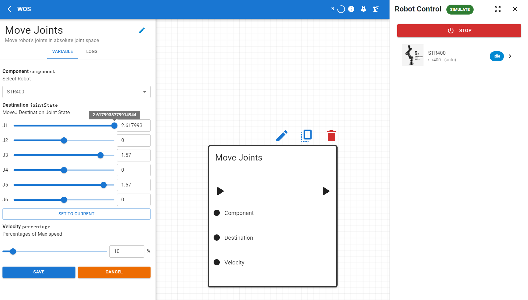
According to the manufacturer's manual, we have configured the corresponding joint ranges for each robotic arm during the adaptation process. These joint limits can be accessed via API requests, but a more intuitive method is available through the user interface. For example, when using the Move Joints node, the sliders for each joint visually represent the hardware’s angle limitations. The image below illustrates the STR400's J1 joint, which is set to a maximum of approximately 2.618 radians.

Speed Limit Configuration
Similarly, information about speed limits is also integrated into the system during setup. The Velocity percentage shown in the image indicates the percentage of the motor's peak velocity used during operations. This setting allows precise control over the speed at which the joints move.
⚠️ Warning: Caution! The maximum speed of the motors is generally measured under no-load conditions. It is advisable to start testing at 10% or in a simulation environment and gradually increase the speed. In most cases, operating at 100% of the speed is not recommended and could pose risks to both the hardware and safety.