Quick Start
Let's discover WOS in less than 10 minutes.
Download and Installation
To get started with WOS, follow these steps to download and install the software:
- Request Access:
- To become a beta tester, please send an email to info@wingsrobotics.com requesting access. We aim to provide prompt responses with further instructions to help you get started.
- Download and Install:
- Upon receiving our email, visit b.wingsrobotics.com to access the download portal. Select the client version that corresponds to your operating system and hardware specifications.
- Download the software and follow the installation instructions to properly set it up on your machine. Once installed, activate the software to unlock all its features and start using it effectively.
Run WOS
Linux & Mac
Follow these steps to set up and run WOS on Linux and Mac operating systems:
- Change directories to the folder where the WOS file was downloaded. For example:
cd ~/Downloads
- Before running the software, you need to make the executable file permissions. Run the following command:
chmod +x wos_v0.1.2-rc1_linux_amd64
- To start the software, use the ./ prefix to execute the program file from the current directory:
./wos_v0.1.2-rc1_linux_amd64
Replace wos_v0.1.2-rc1_linux_amd64 with the actual file name of the downloaded software, which might vary based on the version and the release candidate number.
You can type this command into Command Prompt, Powershell, Terminal, or any other integrated terminal of your code editor.
Windows
Follow these steps to set up and run WOS on Windows operating systems:
- Press Win + R to open the Run dialog, type cmd, and press Enter, or search for "Command Prompt" in the start menu and open it.
- Use the cd command to navigate to the folder where the WOS file was downloaded. For example:
cd Downloads
- Simply type the executable file's name to run it. If the file name is wos_v0.x.x-rcx_windows_amd64.exe, you would type:
wos_v0.1.2-rc1_windows_amd64.exe
Replace wos_v0.1.2-rc1_windows_amd64.exe with the actual file name of the downloaded software, which might vary based on the version and the release candidate number.
Verification
- Upon successful startup, you should see a message similar to the following in your command prompt window:
Apr 22 00:28:45.216 INFO Core: Initialize WOS Core
Apr 22 00:28:45.231 INFO Core: PORT port=15117 RuntimeFPS=60
Apr 22 00:28:45.231 INFO Core: RT control enabled=false base frequency=300
Apr 22 00:28:45.231 INFO Core: Build version=v0.1.2-rc1
Apr 22 00:28:45.231 INFO Core: Path Root Dir=C:\Users\xxxx/.wos Workspace=C:\Users\xxxx/.wos/workspace
Apr 22 00:28:45.231 INFO Core: Debug debug=false
Apr 22 00:28:45.233 INFO System: [MQTT API] MQTT API NOT enabled
Apr 22 00:28:45.233 INFO System: Removing ALL WOS Containers...
Apr 22 00:28:45.249 INFO System: WebService start @ URL:=http://localhost:15117
Apr 22 00:28:45.266 INFO System: WebService start @ http://192.168.179.1:15117
Apr 22 00:28:45.266 INFO System: WebService start @ http://192.168.17.1:15117
Apr 22 00:28:45.266 INFO System: WebService start @ http://10.0.0.92:15117
WOS UI
Accessing WOS UI
After successfully launching the WOS backend, the next step is to access its User Interface through a web browser. Here are the detailed steps:
- It is recommended to use Google Chrome to access the WOS UI for optimal compatibility and performance.
- if you are running the WOS backend on your local machine, use the following URL to access the UI:
http://localhost:15117
- If your device is connected to the same local network as the machine running the WOS backend, access the UI using the machine's IP address followed by the port number 15117. For example:
http://192.168.179.1:15117
Replace 192.168.179.1 with the actual IP address of the machine where the WOS backend is running.
Main Page
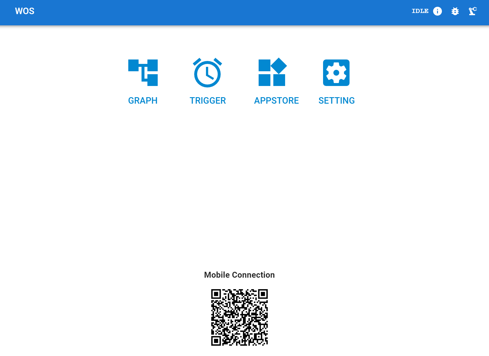
Once the WOS backend is successfully launched, you will be greeted by the interface shown above. The UI is divided into several sections, each designed for specific functionalities:
-
Graph:
- This is a low-code programming interface that utilizes WOS ’s functional modules for motion editing across multiple robot components.
-
Trigger:
- This section allows for the external invocation of pre-set functional modules or pre-edited graphs. Currently, it includes features like scheduled execution of modules or graphs, with more functionalities to be added progressively.
-
Appstore (Under Development):
- In the future, this will enable third parties — whether individuals or companies — to publish easy-to-use apps tailored for various end-user scenarios involving robotic arms.
-
Settings:
- Here, you can adjust general settings for WOS, manage licenses, deploy robot hardware, update software, and modify declarations.
-
Icons
- In the WOS UI, the top-right corner features three icons, each providing quick access to specific functionalities:
- Computer Info - This icon gives you quick access to information about the computer system on which WOS is running. It includes details like CPU load, memory usage, and system uptime.
- Debug (Hidden by Default) - The debug icon is used to access debugging tools and logs. This feature helps in troubleshooting and fine-tuning the performance of applications.
- Robot Hardware Quick Actions - This icon provides shortcuts to frequently used actions related to robot hardware, such as connecting or disconnecting hardware, real-time control, and Visualize robots' states.
- In the WOS UI, the top-right corner features three icons, each providing quick access to specific functionalities:
-
Mobile Connection
- On the WOS UI, navigate to the Mobile Connection section where the QR code is displayed. Use a mobile device within the same local network as the WOS server.
- Open the QR code scanner app (most camera apps have built-in scanners) and scan the QR code displayed on the screen.
- Select the Correct IP Address: After scanning the QR code, if multiple IP addresses appear as connection options (typically labeled as IP Address 1, IP Address 2, etc.), you will need to try each one to establish a connection. This step is necessary due to browser behavior limitations that may not automatically select the most optimal IP address.
Have fun with Virtual STR400 Robot
This section guides you through the process of operating a virtual STR400 robot within the WOS interface to familiarize yourself with its functionalities. Follow these steps carefully to ensure a smooth experience.
Initial Setup
-
Navigate to the Settings Page:
- Open the WOS UI and go to the Settings page by selecting the settings icon from the main page.
-
Verify Your License:
- Locate the License tab within the Settings page. Check to see if there is a valid license listed. The license should look something like this:
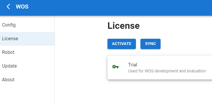
- If no valid license appears, you need to obtain one:
- Email info@wingsrobotics.com requesting a license.
- Once you receive the license, activate it by entering the license key provided in the appropriate field and clicking the
Activatebutton.
Adding a Robot
This section details the steps to add an STR400 robot to your WOS setup. Follow these instructions to configure the robot correctly in the WOS interface.
- Accessing Robot Settings
- Open the WOS UI and select the Settings icon from the main page.
- Go to the Robot tab where you can manage multiple robots.
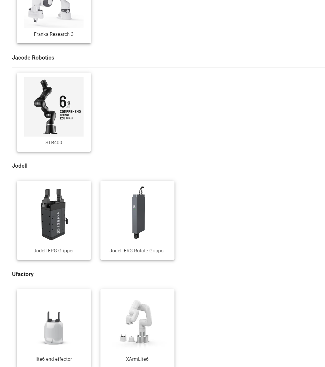
- Click the + icon to add a new robot configuration. This action opens the configuration interface as shown below:
-
Configuring the STR400
-
Naming the Component
- Click on the STR400 icon to proceed with specific configurations for this model.
- Assign a name to this robot component. This name will help you identify this specific hardware in your deployment environment.
- Example Name: STR400_Unit_1
- If multiple STR400 units are added, distinct names (e.g., STR400_Unit_2) will help distinguish between them.
-
EETransform Option
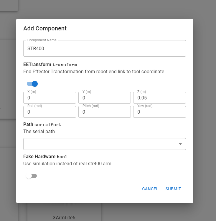
- If an end-effector is installed, select the
EETransformcheckbox. - Configure the 6D coordinate transformation from the robot's last joint to the end-effector ’s tip. For instance:
- Example Setting: For an end-effector 0.05m long, the other positions unchanged.
- If an end-effector is installed, select the
-
Path Selection
- For Real Hardware: Choose the appropriate USB port from the dropdown menu to connect to a real STR400 robot.
- For Simulation: Leave the path selection blank if you are setting up a simulation.
-
Fake Hardware Option
- Disable the Fake Hardware option unless you are testing the controller's robustness in a purely virtual environment.
- Enabling this option simulates the robot's operations without activating any physical movements.
-
Submit the Configuration
- Click the Submit button to save your settings and add the robot to your WOS environment
-
Verifying Robot Configuration
- Return to Robot Settings by click
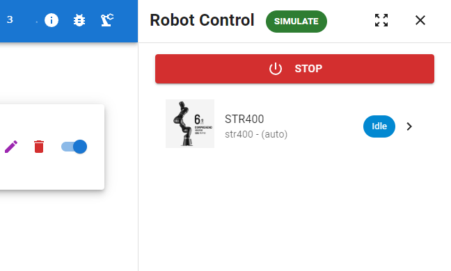
Xon the top of the configuration page. - Click on the Robot tab to view the list of configured robots. Here should be what expected to see:

- Understanding Component ID
- Each component is assigned a unique identifier, such as
7eeb2010-d0b1-4494-86b1-efa136212fa1. This Component ID is crucial for interfacing with external APIs to perform operations on this specific robot.
- Each component is assigned a unique identifier, such as
- Action Icons
- Edit: Click this icon to modify the component's settings if you need to change any configuration details.
- Delete: Use this icon to remove the component from your WOS setup. Be cautious with this option as it cannot be undone.
- Activation Toggle: This switch controls whether the component should be activated when the 'Start' button is pressed in the main interface. Toggle it according to whether you want the component to participate in operations.
Starting Operations with STR400
After ensuring your STR400 robot component is correctly configured, you can begin operations in a virtual environment or with the actual hardware. Follow these steps to initiate operations from the WOS interface.
Initiating the Robot
-
Access the Quick Actions Panel
- Click on the robot arm icon located at the top right corner of the WOS UI. This action will trigger a sidebar containing quick action buttons.
-
Start the Simulation or Actual Robot
- Within the sidebar, click on the
Simulationbutton to start a virtual STR400. This simulates the robot's operations based on the current configurations and scenarios defined in the Graph interface. - If you are using an actual STR400 robot, ensure it is correctly installed in a safe and appropriate environment before proceeding. Clicking the
Startbutton in this context will activate the real robot.
⚠️ Warning: Prior to activating a real robot, double-check the surrounding area to ensure it is free of obstacles and the robot is installed on a stable surface to prevent accidents.
- Within the sidebar, click on the
-
Shutting Down
- After completing the tasks or tests, shut down the robot or end the simulation through the same sidebar by clicking a Stop or End Simulation button, ensuring all movements cease properly.
⚠️ Warning: Prior to Shutting Down a real robot, please ensure it is back to its
Zeroposition, before shut down, because the joints are becoming passitive when shutting down, it will fall if not in a proper postion.
Real Time keypad control
Control the STR400 robot in real-time using the keypad interface provided in the WOS UI. This section explains how to navigate to this feature and utilize it effectively.
- Accessing Keypad Control
- Press the
>button located to the right of the STR400 component listing to expand the operation interface. - Click on the
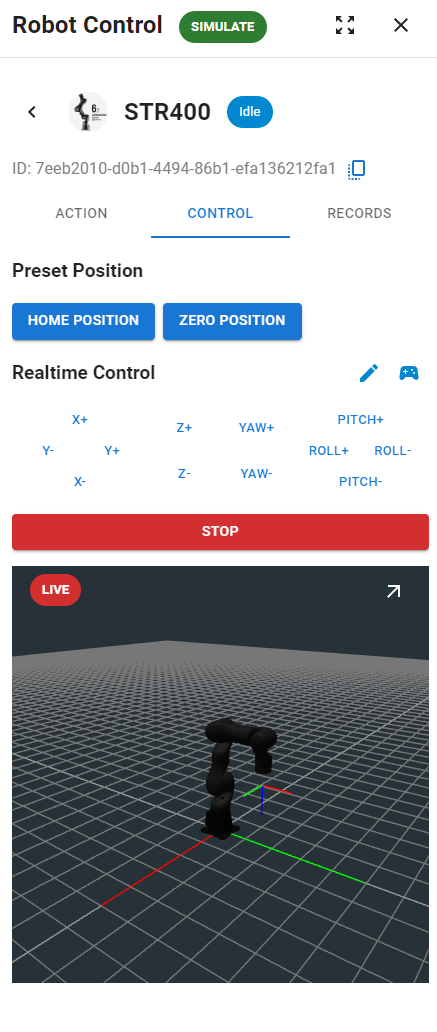
Controltab to open the control interface as shown below:
- Press the
-
Using Preset Positions
- There are two preset positions available: Zero Position and Home Position.
- Zero Position: The robot arm is completely vertical.
- Home Position: The robot arm is in the starting position as illustrated in the interface.
- Click either button to move the robot arm slowly to the selected key position.
- There are two preset positions available: Zero Position and Home Position.
-
Real-Time Keypad Control
- Operate Using the Keypad:
- The keypad allows for real-time control of the robot arm's end-effector in relative space. Below are the detailed functionalities:
- Keypad Buttons: Press the corresponding button to adjust the position of the end-effector by a fixed increment, considering the EETransform settings (e.g., 0.05m end length set during configuration).
- Operate Using the Keypad:
-
Monitoring Arm Status
- Real-Time Rendering:
- A miniaturized real-time render of the robot arm is displayed, showing its current state.
- The interface illustrates:
- Red Line on the Floor: Represents the global X-axis.
- Green Line: Indicates the Y-axis direction.
- End-Effector Coordinate System: Displays the position of the end-effector.
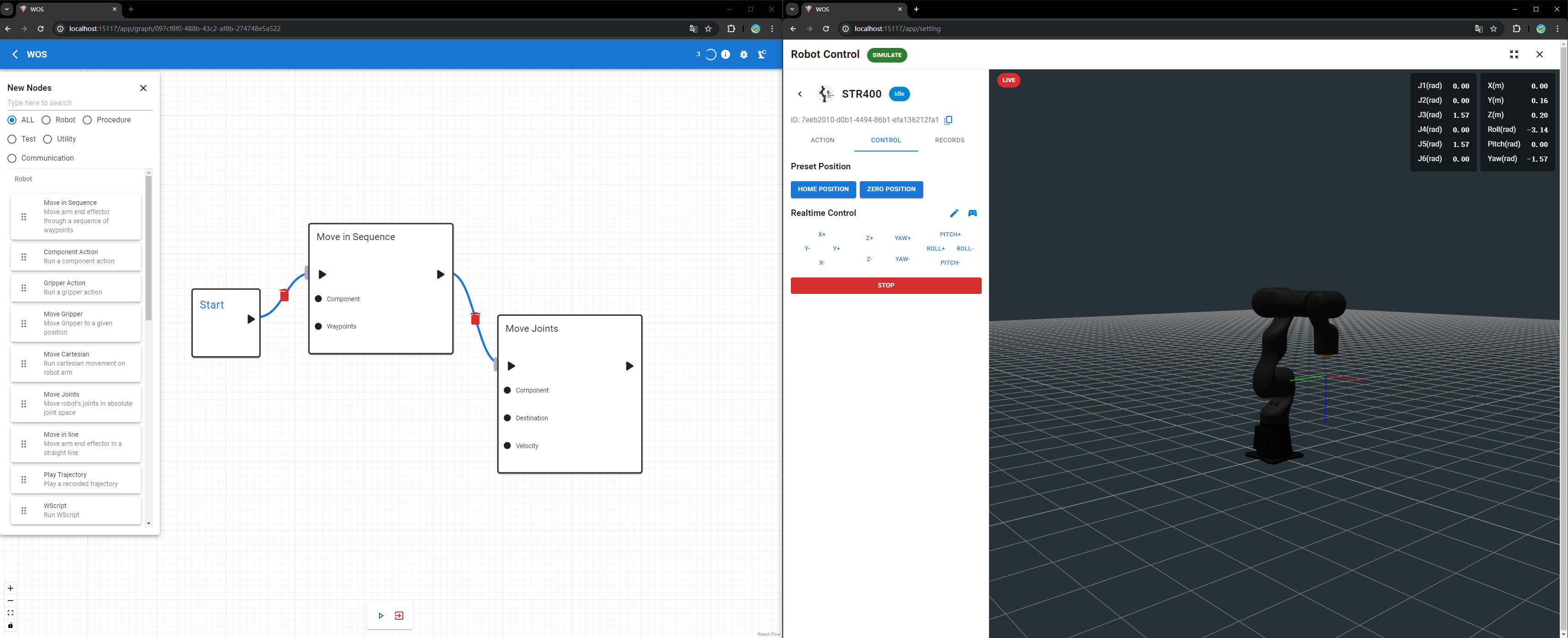
- Clicking on arrow at top right conner on the rendering screen, brings you to a full-screen page of the quick control panel. We highly recommend you to open up two windows of brower to obtain the best experience when developing a
Graphproject:
- Real-Time Rendering:
- Adjusting Control Settings
- Global vs. Relative Control:
- By default, the control is set to adjust the end-effector's position relative to its current position (relative increments in six dimensions).
- To switch to global coordinate control:
- Click the 🖊 icon to edit settings.
- Disable the
Relative?option to use global coordinates for control.
- Global vs. Relative Control:
Your First Graph Project
To begin creating graph projects with WOS, follow these straightforward steps:
-
Navigate to the Graph Page
- From the home page, click on the Graph button to enter the Graph page.
-
Create a New Graph
- Click the + icon to start a new graph. Provide a name and a description for your graph. These are just for your reference and can help you organize your projects better.
- Click Submit to create your graph. Once submitted, a new graph project will be established.
-
Enter the Graph Editor
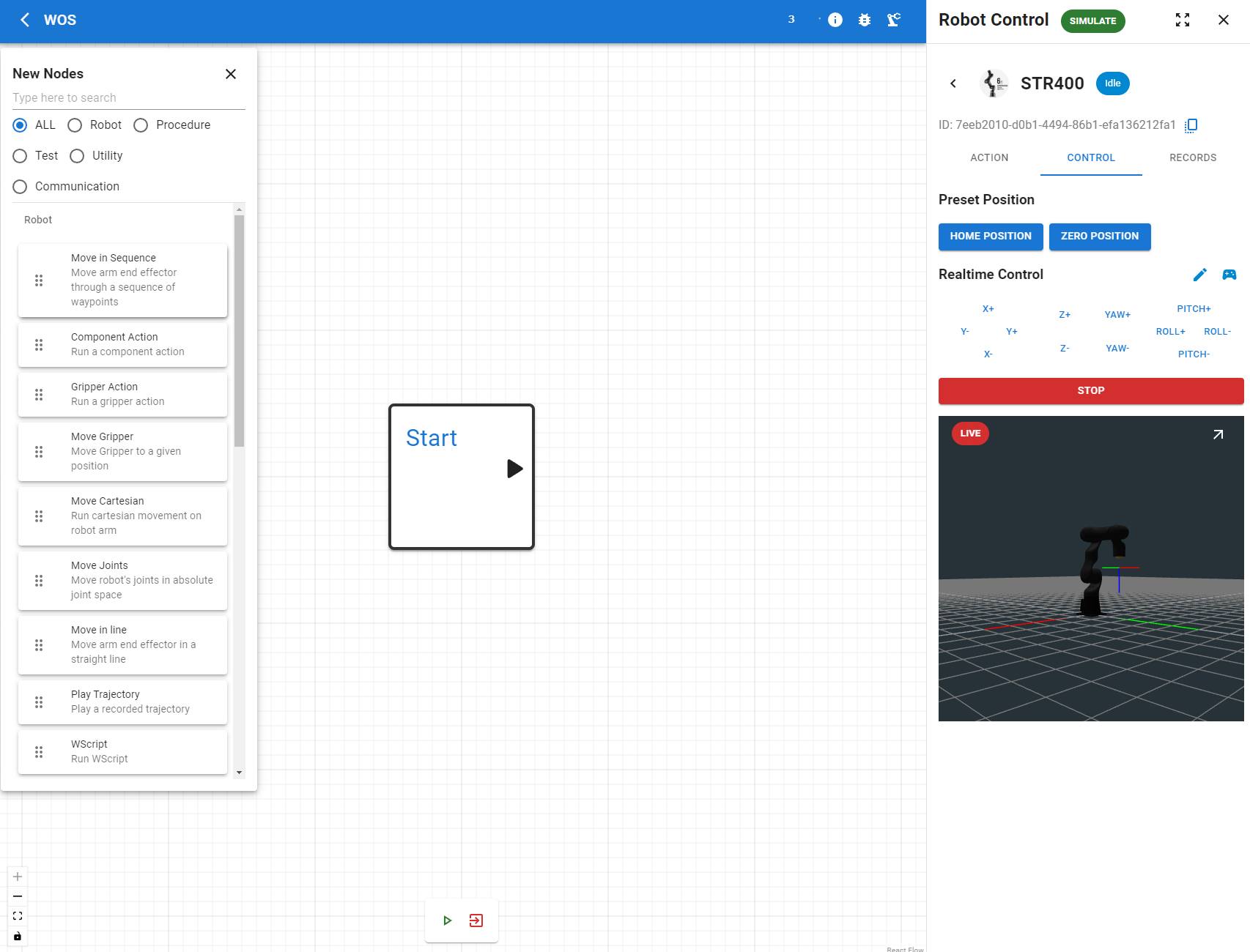
- Click on the purple graph-style icon to enter the graph editing interface.
- Click the green
+icon in the top left corner to open the drawer containing all the functional modules provided by WOS. - To hide this toolbar, simply click the
Xat the drawer's edge.
- Setting Up the WScript Module
- Adding the WScript Module:
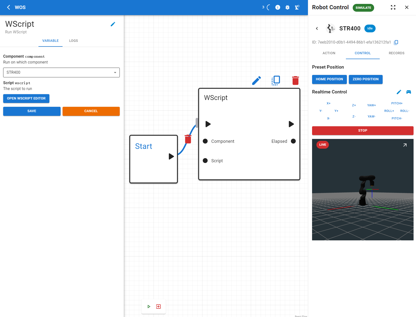
- From the module drawer, drag the WScript module into the drawing area.
- Connect this module to the Start module. The Start module acts as the entry point of the graph project, and any connected module will execute once the play button is pressed.
- Adding the WScript Module:
-
Configuring the WScript Module:
- Click on the WScript module to open its parameter settings window.
- Select the Started Real Robot Component/ Simulated Robot Component, in our case it is STR400
- And then, click on
OPEN WSCRIPT EDITORThis is where you can configure the specifics of the robotic arm movements—complex, smooth, and precise actions can be programmed here. - Copy the WScript provided below, paste this script into the text box in the WScript editor window.
A:MOVEJ 0,1.047,2.094,0,-1.570,0,6
R:MOVEL 0,0,0.150,0,0,0,2
R:MOVEL 0,0,-0.100,0,0,0,1.5
R:MOVEL 0,0.200,0,0,0,0,2
R:MOVEL 0,0,-0.200,0,0,0,2
R:MOVEL 0,0,0.150,0,0,-1.570,2
R:MOVEL 0.400,0,0,0,0,1.570,4
R:MOVEL 0.180,0,0,0,0,1.570,2
R:MOVEL 0.400,0,0,0,0,0,8
A:MOVEJ 0,0,1.570,0,1.570,0,4
R:MOVEJ 0.785,0,0,0.785,0,0,2


R:MOVES 0,0,0,0,-0.261,0,1
R:MOVES 0,0,0,0,0.261,0,1.5
R:MOVES 0,0,0,0,0,0,1
R:MOVES 0,0,0,0,-0.2617993878,0,1
R:MOVES 0,0,0,0,0.2617993878,0,1.5
R:MOVES 0,0,0,0,0,0,1
R:MOVEL 0,0,0,-0.7853981634,0,0,2
R:MOVEL 0,0,0.150,0,0,0,2

R:MOVEL 0.150,0,0,0,0,0,3
R:MOVEL -0.150,0,0,0,0,0,2
R:MOVEL 0,0.150,0,0,0,0,2
R:MOVEL 0,-0.150,0,0,0,0,2

A:MOVEJ 0,0,1.5707963268,0,1.5707963268,0,5
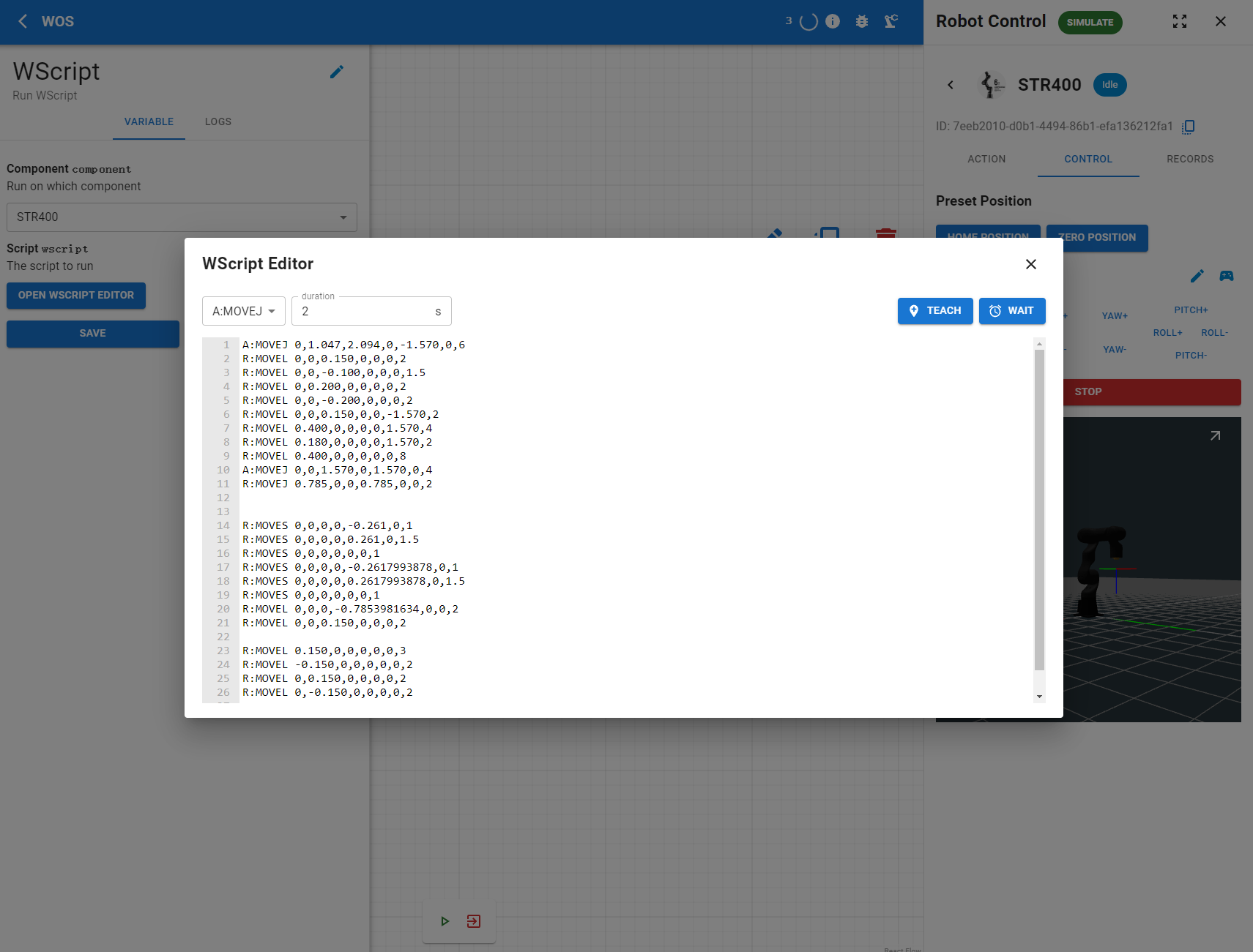
The script you've just input instructs the STR400 to execute a series of movements that culminate in a dance, showcasing the robot's flexibility and range within its operational workspace.
For a more detailed understanding of how to write and implement WScripts, refer to the Documentation provided in the WOS DOC.
-
Save and Exit the Editor:
- Click the
Xbutton to close the editor once you have pasted the script. - Press the
SAVEbutton to save the changes to your graph settings.
- Click the
-
Activating the Graph:
- Once your modules are configured and connected, press the green triangle play button at the bottom of the screen to start the simulation or execution of the graph.
-
Congratulations on Completing Your First Graph Project!
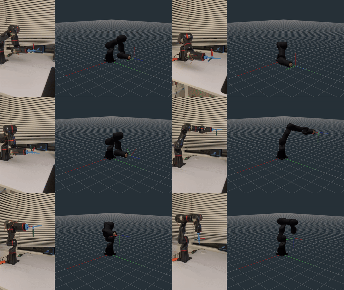
If you see the STR400 moving as shown in the gif below, you have successfully completed your first simple graph project. You're now ready to delve deeper into the WOS graph system!
Next Steps
Now that you've had a hands-on introduction to creating graph projects, you're set to explore more sophisticated aspects of the WOS system. The Documentation contains comprehensive and advanced operational features of Graph functionality that will allow you to further enhance your skills.