Wiring and Electronics Assembly 🔌
ℹ️ Note:
Throughout this document, items in parentheses (e.g., (p)) refer to their corresponding material list identifiers.
In this section, we will prepare the wiring and electronics for the Delta6 system.
The Arduino Nano Every (p) is used to parse SPI signals from the encoders (i) and communicate with the PC via serial at up to 100 Hz.
For detailed communication protocol, please refer to the Firmware chapter.
1. Arduino Nano Wiring
Steps:
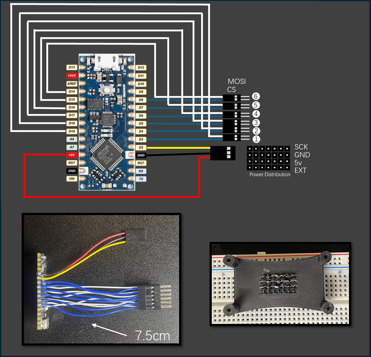
1️⃣ Prepare colored 28 AWG wires (m), each cut to approximately 7.5 cm in length.
2️⃣ Solder one end of each wire onto the Arduino Nano Every (p) according to the figure above.
3️⃣ For the 5V, GND, and D2 pins, assemble them into a 3-pin female connector (b, c).
4️⃣ For the encoder SPI connections, match the pins as follows:
| Encoder | Chip Select (CS) | Data Input (MOSI) |
|---|---|---|
| Encoder 1 | D3 | D19 |
| Encoder 2 | D4 | D18 |
| Encoder 3 | D5 | D17 |
| Encoder 4 | D6 | D16 |
| Encoder 5 | D7 | D15 |
| Encoder 6 | D8 | D14 |
Each encoder uses a unique pair of pins: one CS pin for selection, and one MOSI pin for data input.
Wiring Rule:
- D3–D19 pair → connect to Encoder 1
- D4–D18 pair → connect to Encoder 2
- D5–D17 pair → connect to Encoder 3
- D6–D16 pair → connect to Encoder 4
- D7–D15 pair → connect to Encoder 5
- D8–D14 pair → connect to Encoder 6
📌 Reminder: Be careful to keep the CS and MOSI wires paired correctly, otherwise the encoders will not communicate properly.
2. Power Distribution Board Assembly
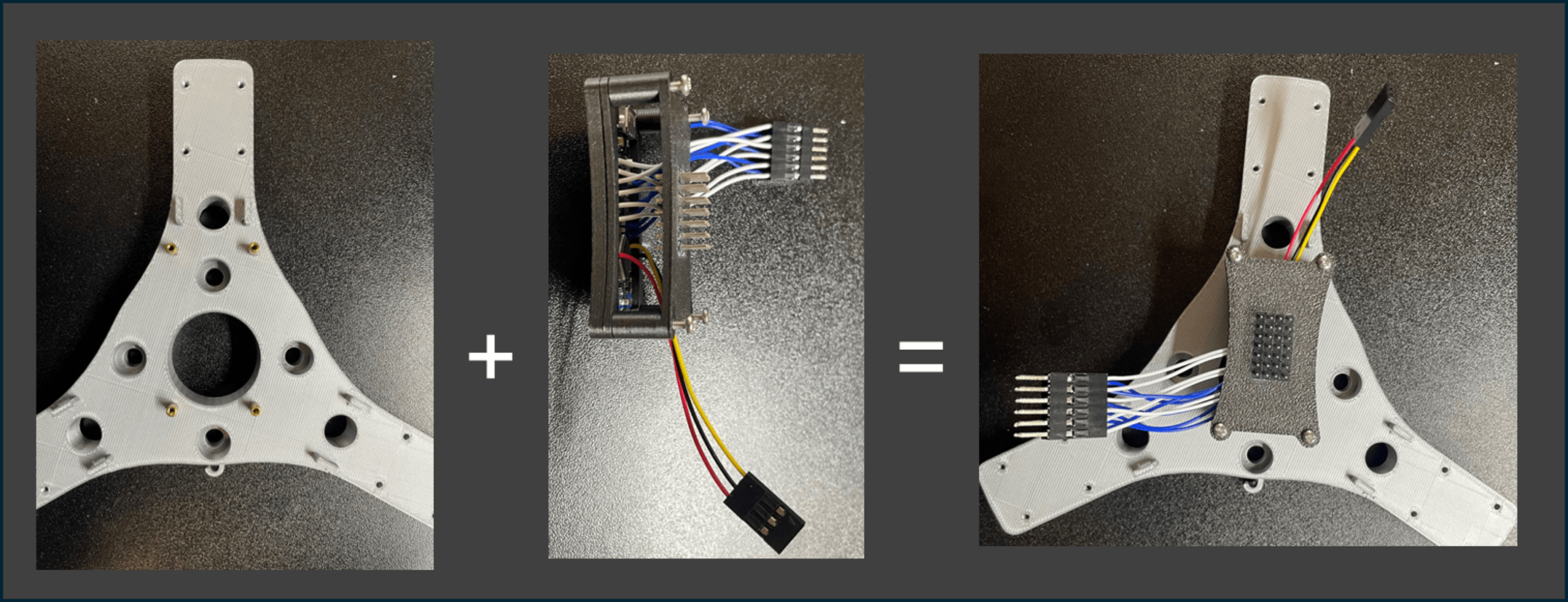
Steps:
1️⃣ Prepare GPIO pin headers (a) and arrange them into a 4×7 grid.
2️⃣ It is recommended to insert the headers into a breadboard to maintain alignment during assembly.
3️⃣ Once properly arranged, glue them together firmly using strong adhesive.
4️⃣ Electrically connect the following rows individually:
- SCK row
- GND row
- 5V row
This arrangement allows all six encoders to share the same power supply and SCK signal.
⚡ Tip: Always verify connections with a multimeter before powering up the system!
Next Step: After wiring is completed, proceed to connect the encoders and test the communication! 🚀