Step-by-Step Assembly Instructions 🛠️
This section provides a detailed, step-by-step guide for assembling the Delta6 mechanical and electronic modules.
1. Microcontroller Module Assembly
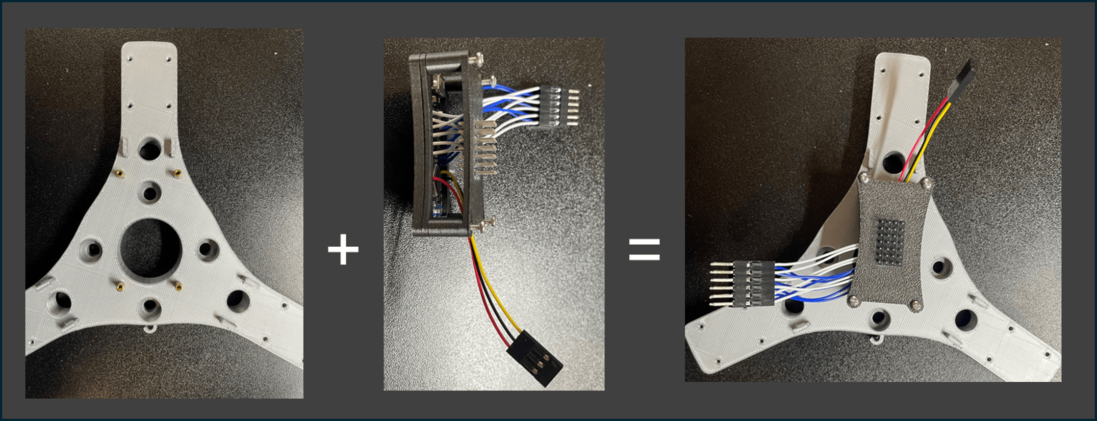
Steps:
1️⃣ Use 4× M2 standoffs (o) and 4× M2×20mm screws to mount the following parts together in a stack:
- Nano Holder 1 (12)
- Nano Holder 2 (13)
- Power Distributor Holder (11)
2️⃣ Attach the stacked module onto the Arm Mount (1) as shown.
3️⃣ Carefully arrange the wiring as indicated in the figure to avoid future interference.
📌 Note: Keep all wires as organized as possible following the reference image.
2. Limb and Spring Assembly
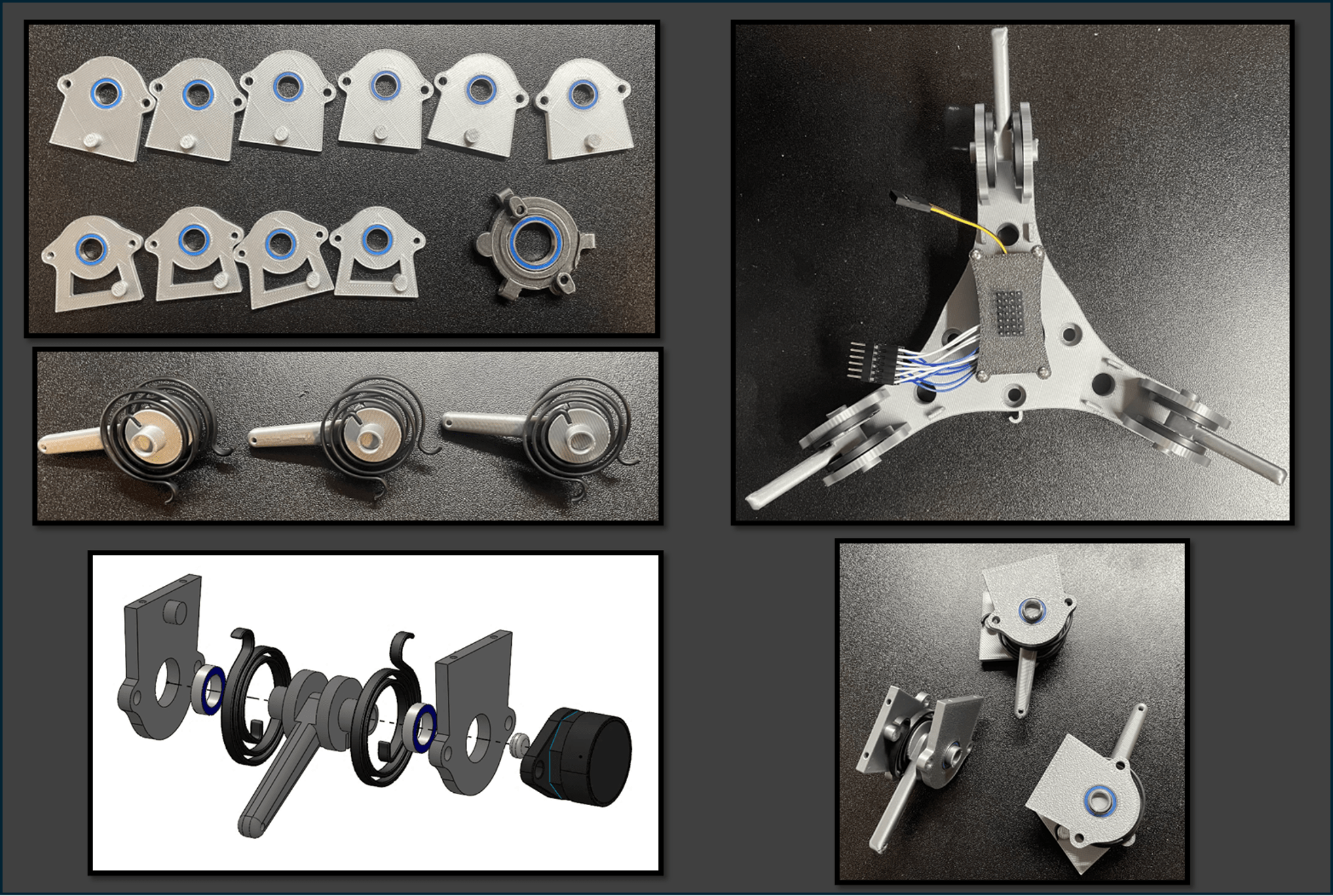
Steps:
1️⃣ Press-fit the bearings (f, g) into:
- Bearing Housing (XYZ) (3)
- Bearing Housing (Roll/Pitch) (2)
- Bearing Housing (Yaw) (10)
🧩 Tip: If the fit is loose, secure the bearings with a small amount of strong adhesive.
2️⃣ Press the springs (d) onto each Limb (4) as shown, forming three spring-loaded limbs.
3️⃣ Assemble the bearing housings together according to the figure.
4️⃣ Fix the limb structures onto the Arm Mount (1) using M2×20mm screws.
📸 After assembly, the structure should look exactly like the top-right image.
3. Universal Joint Module Assembly
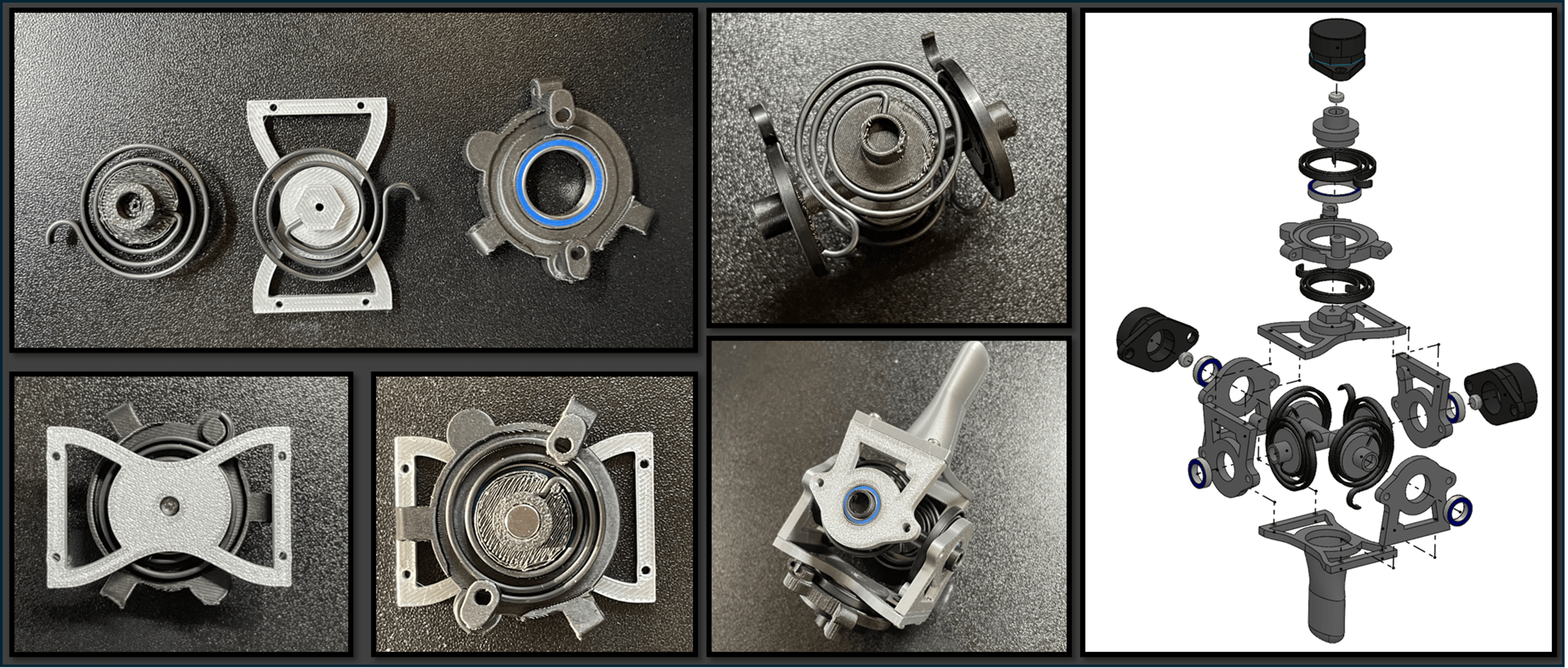
Steps:
1️⃣ Install a spring (d) onto each of the following parts:
- Shaft (Yaw) (9)
- Universal Joint (Upper) (5)
Ensure the spring orientation strictly matches the figure.
2️⃣ Assemble the Shaft (Yaw), Universal Joint (Upper), and Universal Joint (Lower) (6) using an M2×20mm screw, aligning them as shown.
3️⃣ Press-fit a circular magnet into the top of Shaft (Yaw) (9) before proceeding, as this area will become inaccessible later.
4️⃣ Press-fit four springs onto the Shaft (Roll/Pitch) (8), matching the exact orientations shown in the figure.
5️⃣ Assemble the complete Roll-Pitch-Yaw spring mechanism.
6️⃣ Fix the Bearing Housing (Roll/Pitch) using M2×8mm screws.
📌 Important: Carefully follow the orientation shown to ensure proper force sensing directions.
4. Connecting Upper and Lower Assemblies
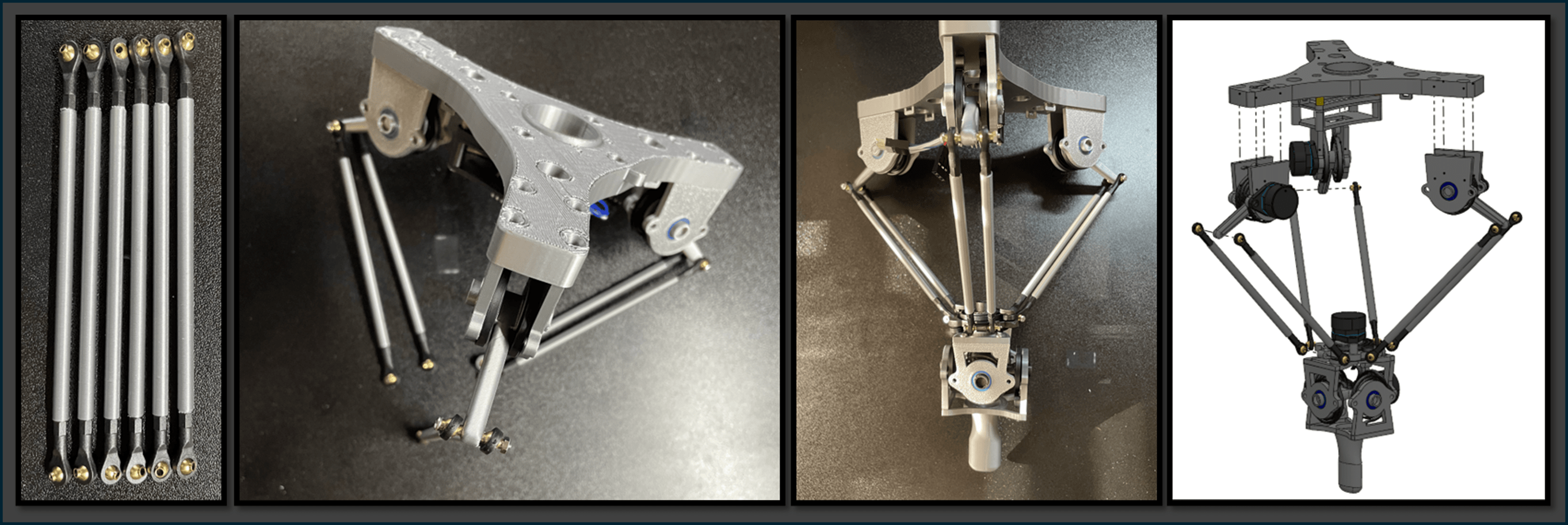
Steps:
1️⃣ Insert six M2×100 rods (q) into the Long M2 Covers (7).
2️⃣ Attach an M2 Ball Head (e) to each end of the rods.
🎯 The Ball Heads must be parallel and the Long M2 Covers must be secure, with no looseness.
3️⃣ Pair the rods into groups of two and attach them to the Limb modules (4).
4️⃣ Finally, connect the rods to the Universal Joint Module using M2×20mm screws and nuts.
📌 Note:
Ensure that the relative orientation between the Universal Joint and the Arm Mount (1) matches the figure exactly.
Incorrect installation will lead to misaligned force sensing axes.
5. Encoder Installation
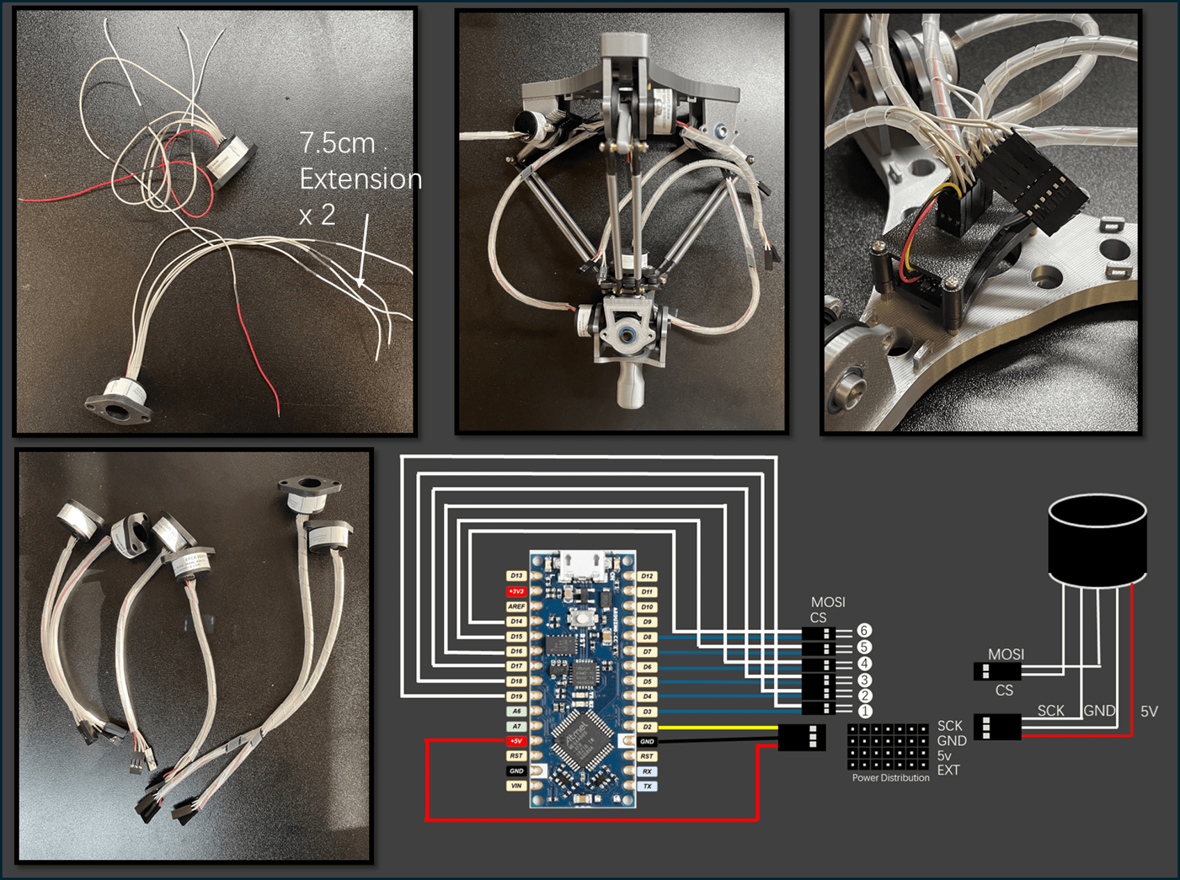
Steps:
1️⃣ Prepare six ERCK 05SPI 360 Encoders (i).
Extend the wires of two encoders by approximately 7.5 cm using Colored 28 AWG Cables (m).
2️⃣ Group and connect the wires as follows:
- Group 1 (3-pin connector): 5V → GND → SCK
- Group 2 (2-pin connector): MOSI → CS
🎨 Wiring Order:
The rightmost wire (red mark) is 5V, followed by GND, then SCK, MOSI, and CS from right to left.
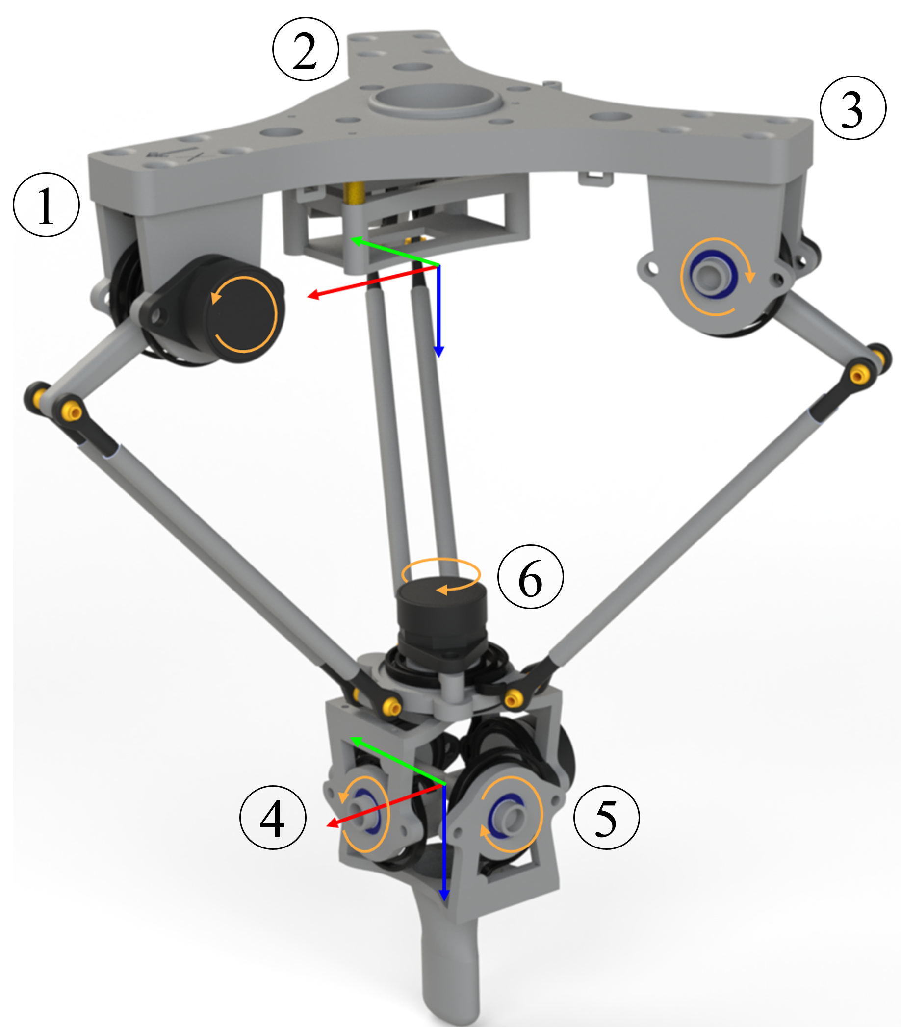
3️⃣ Install the six encoders to the positions shown in the diagram.
Use:
- M3×6mm screws for general mounting
- M4×6mm screws for specific positions as indicated
- Encoders with extended cables should be installed at positions 4 and 5.
4️⃣ Final wiring:
- Insert 3-pin headers into the Power Distribution Board.
- Connect 2-pin headers to the 6×2 connector.
Final Encoder Pin Mapping:
| Encoder | Chip Select (CS) | Data Input (MOSI) |
|---|---|---|
| Encoder 1 | D3 | D19 |
| Encoder 2 | D4 | D18 |
| Encoder 3 | D5 | D17 |
| Encoder 4 | D6 | D16 |
| Encoder 5 | D7 | D15 |
| Encoder 6 | D8 | D14 |
📌 Reminder:
Ensure that the wiring order is strictly followed to avoid communication errors.
🎉 Congratulations!
You have successfully completed the mechanical and electronics assembly!
You can now proceed to the next section: Firmware Installation 🚀